Analysis of Facial Asymmetry
Article information
Abstract
Facial symmetry is an important component of attractiveness. However, functional symmetry is favorable to aesthetic symmetry. In addition, fluctuating asymmetry is more natural and common, even if patients find such asymmetry to be noticeable. However, fluctuating asymmetry remains difficult to define. Several studies have shown that a certain level of asymmetry could generate an unfavorable image. A natural profile is favorable to perfect mirror-image profile, and images with canting and differences less than 3°-4° and 3-4 mm, respectively, are generally not recognized as asymmetry. In this study, a questionnaire survey among 434 medical students was used to evaluate photos of Asian women. The students preferred original images over mirror images. Facial asymmetry was noticed when the canting and difference were more than 3° and 3 mm, respectively. When a certain level of asymmetry is recognizable, correcting it can help to improve social life and human relationships. Prior to any operation, the anatomical component for noticeable asymmetry should be understood, which can be divided into hard tissues and soft tissue. For diagnosis, two-and three-dimensional (3D) photogrammetry and radiometry are used, including photography, laser scanner, cephalometry, and 3D computed tomography.
INTRODUCTION
Owing to growing interest in facial aesthetics, an increasing number of patients have undergone surgery for various skeletal facial deformities. Among these patients, more than half of the Asians showed facial asymmetry, specifically those who were right handed [1234].
Facial asymmetry results from congenital causes such as hemifacial microsomia, environmental causes such as trauma infection tumor, and functional factors such as habit or occlusal interference. Asymmetries from a single cause can have various patterns depending on personal characteristics, onset time, muscular compensation, and musculoskeletal development of the face. Because of these variables, classification facial asymmetry is difficult [56].
Facial symmetry refers to a complete match in size, location, shape, and arrangement of each facial component about the sagittal plane. That is, asymmetry refers to the bilateral difference between such components. A perfect bilateral symmetry almost never exists in the human body [7].
Most complaints regarding the facial unattractiveness can be divided into three aspects, namely the profile, appearance of weightiness, and asymmetry. A number of studies have indicated that symmetry plays an important role in deciding facial attractiveness. However, slight asymmetry can give a more natural perception because minor asymmetry minimizes more severe asymmetry by compensation. Furthermore, such fluctuating asymmetry is more natural and common even if patients are more aware of this asymmetry. Therefore, such level of asymmetry cannot be considered unattractive. Such fluctuating asymmetry is critical and is thought as random deviations from the perfect symmetry in bilateral traits that are, on average, symmetrical at the population level [8].
Fluctuating asymmetry is difficult to define. Distinguishing between what is attractive and unattractive is especially difficult and requires further research.
ASSESSMENT OF FACIAL ASYMMETRY
Soft tissue
Because the shape and movement of soft tissues, rather than the skeleton, are visible during interpersonal interaction, relative assessment of the facial can be considered as most important. No distinctive visible parameters or strategies have been established to distinguish between normal and abnormal asymmetries of the soft tissues. Instead, facial aesthetics are decided based on the subjective perception from patients or physicians. Therefore, subjective evaluations such as the perception of asymmetry of the facial profile will depend on soft tissues [9101112].
The assessment should be systematically conducted as patients are standing or sitting comfortably, in the natural head position and centric occlusion state, with lips in resting state. The natural head position is the head position that patients feel most comfortable. To confirm the proper soft tissue change, patients should relax their lips. For example, patients who have vertical maxillary deficiency and severe malocclusion tend to strain the perioral musculature in compensation. Thus, patients must be assessed in a resting position in order to accurately assess the maxillary incisor-labial relationship. In such cases, patients might be asked to bite wax between their teeth to increase the vertical dimension until the lips are in contact. Significant factors to assess include deficiency of dental show, foam, and lip thickness in relation to the front and back of the jaw, labiomental fold, upper lip length, nasolabial angle, and thickness of soft tissues [213].
Traditionally, the sella-nasion (S-N), and frankfort horizontal (F-H) planes have been used as the horizontal reference plane in various cephalometric and clinical assessments. However, these reference planes do not assume the natural head and neck posture for many patients and do not accurately represent the aesthetic perception throughout daily life. Thus, clinical assessment should be performed in the natural position. Head position in the resting state is important because it is difficult to correct asymmetry resulting from the neck and head position, even though surgery can assure facial symmetry. The presence of asymmetry from an immoderate position must be confirmed before treatment planning [14].
Two-dimensional photogrammetry
Photographic evaluation should assess generalized facial features, symmetry, and relationship among the upper, mid, and lower face, lip, and nose. The vertical and horizontal ratio has a huge impact on the harmony of facial features and need to be compatible with the overall image and whole-body appearance of the individual. The basic facial height and width ration is 1.3:1 in women and 1.35:1 in men. An intergonial width that is 30% less than the interzygomatic width is ideal.
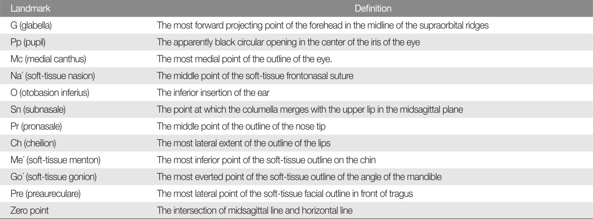
The midsagittal (MRP) line that connects the glabella (G') and subnasale (Sn) is used to assess asymmetry. For highly accurate assessment, the soft tissue landmarks on patient's face should be marked and other features of the face should be masked before photogrammetric assessment (Tables 1, 2; Fig. 1). Most patients do not have perfect facial symmetry, but an unnoticeable asymmetry suggests a good profile. When the asymmetry is clinically obvious, using posterior-anterior cephalometric radiography can be beneficial is caused by the skeleton, soft tissues, or a combination of the two [1112].
Soft tissue landmarks
Soft tissue reference lines

Landmarks on the facial soft tissues. Pp, pupil; O', otobasion inferius; Mc, medial canthus; Ch, cheilion; Go', soft-tissue gonion; Me', softtissue menton; G, glabella; Sn, subnasale; Pr, pronasale; Na', soft-tissue nasion; Pre, preaureculare; MI, midsagittal line; BI, bipupillary line; HI, horizontal line; RI, ramus line; OI, otobasion inferius line; O, oto; GI, gonion line; CI, chin line, Mbl, mandible body line; Pog', pogonion.
Angular measurement
In case of an ideal symmetry, the angular lines are parallel. Therefore, an angle that forms between these lines can indicate the degree of asymmetry. Horizontal and vertical lines are used as the references. In some cases, the median sagittal or bipupillary line is used as a reference line. Vertical reference lines are used specifically for evaluating the midface and lower face (Table 3) [215161718].
Angular and linear measurement
Linear measurement
The degree of asymmetry is measured based on the distance between the reference plane and the same points on both sides. This is an analysis method for the horizontal component. The vertical component is analyzed by distances between lines passing through points on both sides perpendicular to the median sagittal, for which the bipupillary line is used as a horizontal reference line. Both vertical and horizontal reference lines can be used in certain cases [161719].
Three-dimensional photogrammetry
Three-dimensional computed tomography (3D CT) analysis is currently not considered a special procedure and isused for special indications and for craniofacial research. This is because 3D photogrammetry has become robust enough and does not expose patients to any radiation exposure. Three-dimensional photogrammetry can be allows surface anatomy evaluations, fast anthropomorphic calculations, and 3D transformations. It can also be used to confirm symmetry and to analyze outcomes following surgical intervention. However, baseline imaging data are limited and only several pilot studies have been conducted on indirect anthropometry [20212223]. The algorithm behind 3D photogrammetry is based on the iterative closest point calculations. Another major method is a spatially dense anthropometric mask comprised of uniformly sampled quasi-landmarks [2425].
Hard tissues
Two-dimensional (2D) measurement
Posterior-anterior cephalometric radiographic evaluation is important for diagnosis and treatment planning for facial asymmetry. This requires an accurate reference line: one, when using a line passing through the central structures such as the crista galli, nasal septum, anterior nasal spine, and menton as a vertical reference line; and two, when setting the lateral orbitale, in which the orbital and oblique outlines meet, as a horizontal reference line and using the corresponding vertical reference line (Fig. 2). Major analytical methods include Ricketts's and Grummons' analyses (Figs. 3, 4). We use a simple protocol that incorporates advantages of both methods (Fig. 5) [1325].

(A) Posteroanterior cephalometric landmarks. 1, external peripheral cranial bone surface; 2, mastoid process; 3, occipital condyle; 4, nasal septum: crista galli, floor of nose; 5, orbital outline: inferior surface of the orbital plate of the frontal bone; 6, oblique outline: innominate line; 7, superior surface of the petrous portion; 8, lateral surface of the frontosphenoid process of zygoma and zygomatic arch (ZA); 9, cross section of zygomatic arch; 10, infratemporal surface of maxilla; 11, mandible: body, rami, coronoid process, condyles; 12, dental unit. (B) Posteroanterior cephalometric landmarks. Om, orbital midpoint, the point of the line connecting the right and left lo (lateral orbitale) at the base of the cristagalli that the highest point on the extenstion of the nasal septum, the reference point of sagittal plan; mo, medial orbitale, the nearest point on the medial orbital margin in median plan; tns, tip of nasal spine; ans, anterior nasal spine, the center point at the base of the nose; iif, incision inferior frontale: the central point of the mandibular central incisors end; isf, incision superior frontale: the central point of the maxillary central incisors end; m, mandibular midpoint; lo, lateral orbitale, lateral orbital margin and innominate line that intersects; lzmf, lateral zygomatic frontal suture; mzmf, medial zygomatic frontal suture; cd, condylion, the hightest point of mandibular condyle; za, most lateral point of zygomatic arch; ma, lowest point of mastoid process; ag, antegonion, the highst point of antegonial notch; mx, maxillare, the line between maxillary alveolar process and inferior point of ztgomatic buttress. Similar with J point; J jugulare (J), the most concave point of zygomatic buttress; um, maxillary molar, the outer surface of the maxillary first molar; lm, mandibular molar, the outer surface of the mandibular first molar; mf, mental foramen; CSP, cental sagittal plan. Draw in several ways, representative example, vertical line of lo-lo line is passing through plotting the om, passing drawing a vertical line of the line connecting the two sides lzmf and zmmf is om.

Ricketts analysis: based on the draw CSP, and analyzed by measuring the relative distance and angle of the respective measurement points. 1) Nasal cavity width: NC-NC, the distance between the outermost point of the nasal cavity. 2) Mn. width: AG-AG, the distance between antegonial notch. 3) Mx. width: the distance between Z-AG and J. 4) Symmetry the distance between the left and rgith ZA, AG on CSP, the relationship. Between CSP and m, the distance and angle between the left and right J on CSP. 5) Intermolar width: the distance and angle between um and lm on CSP. 6) Intercuspid width: the distance and angle between tip of mandibular canine and CSP. CSP, central sagittal plane; ZA AXIS, zygomatic arch axis; NC, nasal cavity; AG, angle of gonion or gonial notch.

Grummons analysis. Measurement plane: 1) Z plan: the line connecting the left and right mzmf. 2) ZA plan: the line connecting the left and right za. 3) J plan: the line connecting the left and right J point. 4) Occlusal plan: the line connecting the bite point of the left and right fist molar. 5) AG plan: the line connecting the left and right ag. 6) Menton line: the line parallel to the z plan that passes through the menton.

Kyungpook National University quick protocol for posterioranterior analysis.
The Kyungpook National University (KNU) quick protocol is performed by using posterior-anterior cephalometric radiography:
(1) Find the lateral orbitale, connect both sides, and make a vertical line pass through om to draw central sagittal plane (CSP).
(2) In order to assess the asymmetry of the zygoma, draw a perpendicular line from the CSP to the point of the zygoma on both sides and examine the asymmetry of the top and bottom, and left and right. This is used to determine the extent of zygoma reduction.
(3) To assess the asymmetry of the maxilla, the distance between the CSP and the line connecting the J points on both sides and its angle are measured, and the degree of maxillary asymmetry of the top and bottom, and left and right is examined.
(4) To assess the asymmetry of the mandible, the distance between the CSP and the midline of the mandibular central incisor, or the line connecting the mental spine and menton and its angle is measured to examine the degree of asymmetry from the center of the mandible.
Panoramic radiographic evaluation is a useful method to examine various states of the maxillomandible by obtaining 3D feature of the facial skeleton. It has many advantages, including the ability to accurately assess the shape to avoid inferior alveolar nerve damage, which is a major complication of facial skeleton surgery. Because of this, it is used widely these days, where shape reconstitution is easily conducted using 3D CT.
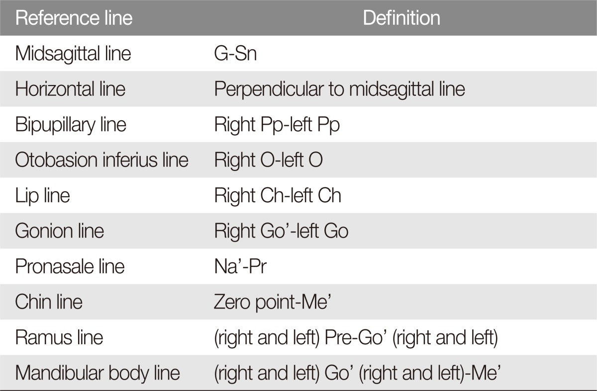
In addition, panoramic radiography allows identification of a deviation resulting from intentional interdental osteotomy, impacted tooth, and pathological conditions that have not been previously observed. Such assessment is significant not only for preoperative diagnosis but also for surgical planning. Furthermore, panoramic radiography can reveal consistent top-to-bottom ratio and allows accurate planning for the amount of osteotomy required (Fig. 6) [13].
(A) Analysis of panoramic radiographic: investigation of mandibular symmetry. (B) Analysis of panoramic radiographic: treatment planning, correction of mandibular rolling. The arrow represents the direction of correction for asymmetry. (C) Analysis of panoramic radiographic: paper surgery according to the treatment planning.
3D measurement
A method that uses a surface scanner is not uncommon these days [24]. The time required for scanning is about 1 minute, which is on par with direct anthropometry. Direct anthropometry and digitizer method require direct contact of the instrument with subject [26]. Noncontact measurement methods include 3D CT, 3D laser scan, and stereoscopic camera. Among these, 3D CT has the best resolution and is capable of 3D facial reconstruction, recoding, and analysis [27]. Both 3D and 2D images are useful for the analysis of asymmetric structures. Although cephalometric radiography allows adequate skeletal analysis, 3D imaging can sometimes generate more accurate assessment and is required in certain cases. Three-dimentional analysis can distinguished in certain features which are not resolvable in 2D images (Table 4).
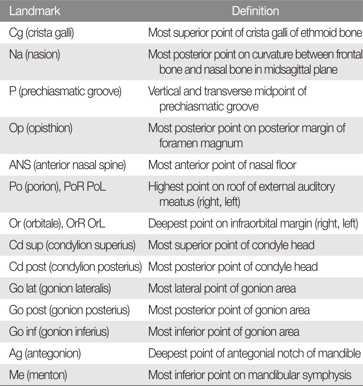
Landmark for three-dimensional computed tomography
The reference plane for 3D image analysis can be defined as follows: horizontal (HRP), MRP, and coronal (CRP). These parameters that are useful for measuring facial asymmetry can be easily defined. Surgeons can know the degree of asymmetry by calculating the differences between the values of these parameters on both sides (Table 5, Figs. 7, 8) [28].

Parameters for assessment of facial asymmetry
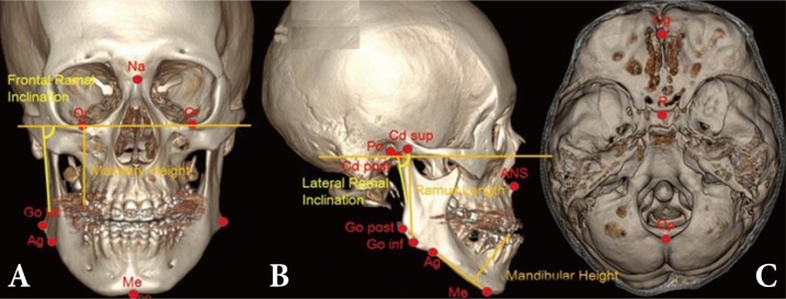
(A-C) Landmarks for three-dimensional computed tomography analysis. Na, nasion; Or, orbitale; Go lat, gonion lateralis; Ag, antegonion; Me, menton; Cd sup, condylion superius; ANS, anterior nasal spine; Cg, crista galli; P, prechiasmatic groove; Op, opisthion.

Reference plan and rotations for three-dimensional measurement.
Occlusion and temporomandibular joint asymmetry
The dental midline is assessed at open bite, centric relation (CR), initial contact, and centric occlusion (CO). Skeletal and dental asymmetries appear similar in the CR and CO states, but functional deviation of mandible occurs after initial contact when asymmetry is caused by occlusal interference. This deviation can be in the same or opposite direction, and the asymmetry can become more prominent or subtle. Temporomandibular joint (TMJ) internal derangement should be evaluated for additional asymmetry.
Because transverse canting of the occlusion plane can result from unilateral development of mandibular condyle or ramus, direct clinical examination is necessary. The slope of occlusal plane can be easily confirmed by asking the patients to bite the tongue blade and comparing the occlusal plane with the inter-pupil line. Any unilateral posterior cross bite must be carefully examined to determine whether the degree of asymmetry in the buccolingual direction results from skeletal, dental, or functional occlusion. In case of mandibular deviation between CR and CO assessment, the mandible must be compared with dental, skeletal, and soft tissue reference points [29].
Articulator analysis uses dental cast of maxilla and mandible on the articulator to examine the degree of asymmetry of the maxilla and mandible relative to the cranium. It determines the degree of deviation of the maxilla-mandible dental midline relative to the occlusal plane, canting, and facial midline, and the degree of rotation and deviation of the occlusion relative to the cranium. In addition, because the difference between CR and CO within the normal range is within a less permissible range in the horizontal plane than in the vertical plane, or in the anterior-posterior plan, the presence of unilateral occlusal contact from CR to CO should also be examined (Fig. 9).

Articular analysis: (A) Face bow transfer. (B) Mounting for upper dental cast. Articular analysis: (C) Frontal view shows pitching of occlual plan. (D) Lateral view shows rolling of occlusal plan. (E) Palatal view of maxillary dental cast, shows yawing of maxilla.
Among many causes of facial asymmetry, functional asymmetry and mandibular shift from occlusal interference and malocclusion can be corrected in children by using orthopedic appliances such as the Frankel appliance, activator, Herbst appliance, and bionator hybrid functional appliance.
What is a fluctuating asymmetry?
Correcting asymmetry is a goal of orthognathic surgery. Although functional asymmetry may be is favored, fluctuating asymmetries are difficult to define, especially between attractive and unattractive [8] and between normal and abnormal. Craniofacial asymmetry is very common and can be found in subjects who consider themselves as having symmetrical head. In addition, soft tissue facial asymmetry is common even in subjects with normal dentition. Therefore, a certain level of asymmetry is commonly observed in the general population.
Studies of the general populations have focused on asymmetries of menton, chin deviation, or gonial angle, and these studies are known to be useful in facial asymmetry research [11]. Facial asymmetry can be recognized if the menton is deviated by more than 4 mm [2930]. Other studies have reported more than 2 mm difference in these points to be recognized as asymmetry [331].
In the context of facial movements, a 3-mm asymmetry was considered abnormal for smiling. Asymmetry was recognized when both the eyebrow and oral commissure have more than a 3-mm difference [32]. In case of lip canting, mandibular chin deviation, body inclination difference, and gonial angle difference, asymmetries were recognized at 3.1, 3.6, 7.1, and 6.1, respectively. Some suggested using these as criteria for the diagnosis of facial asymmetry [11].
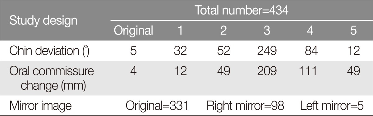
We have created an image that combines pictures of well-recognized Asian faces and conducted a survey among 424 medical students from 2010 to 2013. The students were asked to evaluate the most attractive or symmetrical in three sets of modified photographs along with the original: (1) Mirror-ness: original, left mirror, and right mirror image, (2) Lip-chin canting: original image and 5 images with lip chin canting from 1° to 5°, (3) Oral commissure level: original and 5 images with oral commissure elevated toward the medial canthus from 1 to 5 mm. This was conducted two times, with a 7 day interval. The results showed that students favored the original images with natural asymmetry over the mirror images, which was in line with previous research findings. In addition, 3°-lip chin canting and 3-mm oral commissure change were recognized as the most common asymmetrical pattern (p<0.01) (Table 6, Fig. 10).
Evaluation for composed photography

(A) Mirror image study: left, original composed image; center, right mirrored image; right, left mirrored image. (B) Chin-lip canting study images: most left image, original; most right image, 5° canting. (C) Oral commissure elevation images: most left image, original; most right image, 5 mm elevation.
Step-by-step asymmetry analysis
Asymmetry can be assessed from various angles, but in this study, we used 5 steps in clinical setting. For the basic concept, the outside-in pattern, in which the assessment begins from the outside and proceeds to intraoral dentition, is better than the inside-out pattern for the assessment of facial appearance. It is especially good for the assessment of asymmetry. This is to assess in the order of macroesthetics, miniesthetics, and microesthetics:
(1) Using an upper body image and a frontal facial photo, assess the overall appearance such as gross harmony and asymmetry.
(2) Using a frontal and lateral facial photo, assess the profile, vertical proportions, and facial width. Obtain 3D photographs if necessary.
(3) Make direct and indirect assessments of the occlusion plane and dental midline by taking various photographs.
(4) Make occlusal analysis and TMJ assessment through an intraoral examination and a TMJ analysis.
(5) Take 2D and 3D radiographic images such as frontal and lateral cephalograms, panorama, and periapical view, and dental impression, and verify whether it is consistent with the information previously obtained.
Finally, the direction and extent of asymmetry are measured and verified by combining all of the data. Individual factors such as the tissue and skeletal framework and dental arch coordination are assessed. The cause of asymmetry is also examined.
CONCLUSION
Favorable facial images can have a certain level of asymmetry, and a natural profile is preferred over a perfect-mirror images. Images with canting less than 3°-4° and a difference smaller than 3-4 mm are not recognized as asymmetric in general. This is in line with the results of a previous research study by the author. However, because correction of more severe asymmetry can enhance interpersonal relationships, asymmetry should be accurately diagnosed in a constant outside-in pattern by using 2D and 3D photogrammetry, or radiometry.
Notes
No potential conflict of interest relevant to this article was reported.